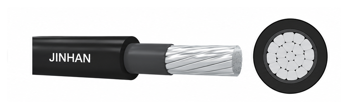
适用于电压等级为 10kV 的架空绝缘电缆。该产品主要用于架空安装条件下的电能分配。导体必须安装在与工作电压相匹配的绝缘子和/或间隔件上。用户在选型时,应考虑绝缘层、绝缘子、间隔件等组件之间的介电兼容性。
导体采用绞合的圆形紧压铝、铝合金或铜材料。导体屏蔽层为挤包的黑色半导电屏蔽层。外绝缘层主要采用黑色热塑性聚乙烯 (PE) 或交联聚乙烯 (XLPE) 材料,具备耐候性或抗紫外线性能。本标准涵盖了热塑性聚乙烯和交联聚乙烯两种结构,其额定正常运行温度分别为 75°C 或 90°C。
Conductor / Insulation Type | No. of Cores | Nominal Cross-sectional Area |
CU/XLPE, AAC/XLPE, AAAC/XLPE | 1 | 10–400 mm² |
CU/XLPE, AAC/XLPE, AAAC/XLPE | 3 | 25–400 mm² |
CU/XLPE, AAC/XLPE, AAAC/XLPE | 3+k(A) or 3+k(B) | Main cores: 25–400 mm²; k: 25–120 mm² |
CU/PE, AAC/PE, AAAC/PE, CU/XLPE, AAC/XLPE, AAAC/XLPE | 1 | 10–400 mm² |
AAC/XLPE, AAAC/XLPE | 3 | 25–400 mm² |
AAC/XLPE, AAAC/XLPE | 3+k(A) or 3+k(B) | Main cores: 25–400 mm²; k: 25–120 mm² |
Note: The source defines k as a load-bearing core. (A) denotes a steel-carrying stranded wire; (B) denotes an aluminum-alloy-carrying stranded wire.
Values below are transcribed from the source webpage. “—” indicates that no value was provided in the source table.
Nominal size (mm²) | Min. no. of wires | Approx. conductor dia. (mm) | Min. conductor-screen thickness (mm) | Reduced nominal insulation thickness (mm) | Nominal insulation thickness (mm) | Insulation-screen thickness (mm) | Max. DC resistance at 20°C — hard Cu (Ω/km) | Max. DC resistance at 20°C — soft Cu (Ω/km) | Min. breaking load (N) |
10 | 6 | 3.8 | 0.5 | — | 3.4 | — | — | 1.830 | — |
16 | 6 | 4.8 | 0.5 | — | 3.4 | — | — | 1.150 | — |
25 | 6 | 6.0 | 0.5 | 2.5 | 3.4 | 1.0 | 0.749 | 0.727 | 8465 |
35 | 6 | 7.0 | 0.5 | 2.5 | 3.4 | 1.0 | 0.540 | 0.524 | 11731 |
50 | 6 | 8.3 | 0.5 | 2.5 | 3.4 | 1.0 | 0.399 | 0.387 | 16052 |
70 | 12 | 10.0 | 0.5 | 2.5 | 3.4 | 1.0 | 0.276 | 0.268 | 23461 |
95 | 15 | 11.6 | 0.6 | 2.5 | 3.4 | 1.0 | 0.199 | 0.193 | 31759 |
120 | 18 | 13.0 | 0.6 | 2.5 | 3.4 | 1.0 | 0.158 | 0.153 | 39911 |
150 | 18 | 14.6 | 0.6 | 2.5 | 3.4 | 1.0 | 0.128 | — | 49505 |
185 | 30 | 16.2 | 0.6 | 2.5 | 3.4 | 1.0 | 0.1021 | — | 61846 |
240 | 34 | 18.4 | 0.6 | 2.5 | 3.4 | 1.0 | 0.0777 | — | 79823 |
300 | 34 | 20.6 | 0.6 | 2.5 | 3.4 | 1.0 | 0.0619 | — | 99788 |
400 | 53 | 23.8 | 0.6 | 2.5 | 3.4 | 1.0 | 0.0484 | — | 133040 |
Nominal size (mm²) | Min. no. of wires | Approx. conductor dia. (mm) | Min. conductor-screen thickness (mm) | Reduced nominal insulation thickness (mm) | Nominal insulation thickness (mm) | Insulation-screen thickness (mm) | Max. DC resistance at 20°C — AAC (Ω/km) | Max. DC resistance at 20°C — AAAC (Ω/km) | Min. breaking load — AAC (N) | Min. breaking load — AAAC (N) |
10 | 6 | 3.8 | 0.5 | — | 3.4 | — | 3.080 | 3.574 | — | — |
16 | 6 | 4.8 | 0.5 | — | 3.4 | — | 1.910 | 2.217 | — | — |
25 | 6 | 6.0 | 0.5 | 2.5 | 3.4 | 1.0 | 1.200 | 1.393 | 3762 | 6284 |
35 | 6 | 7.0 | 0.5 | 2.5 | 3.4 | 1.0 | 0.868 | 1.007 | 5177 | 8800 |
50 | 6 | 8.3 | 0.5 | 2.5 | 3.4 | 1.0 | 0.641 | 0.744 | 7011 | 12569 |
70 | 12 | 10.0 | 0.5 | 2.5 | 3.4 | 1.0 | 0.443 | 0.514 | 10354 | 17596 |
95 | 15 | 11.6 | 0.6 | 2.5 | 3.4 | 1.0 | 0.320 | 0.371 | 13727 | 23880 |
120 | 18 | 13.0 | 0.6 | 2.5 | 3.4 | 1.0 | 0.253 | 0.294 | 17339 | 30164 |
150 | 18 | 14.6 | 0.6 | 2.5 | 3.4 | 1.0 | 0.206 | 0.239 | 21033 | 37706 |
185 | 30 | 16.2 | 0.6 | 2.5 | 3.4 | 1.0 | 0.164 | 0.190 | 26732 | 46503 |
240 | 34 | 18.4 | 0.6 | 2.5 | 3.4 | 1.0 | 0.125 | 0.145 | 34679 | 60329 |
300 | 34 | 20.6 | 0.6 | 2.5 | 3.4 | 1.0 | 0.100 | 0.116 | 43349 | 75411 |
400 | 53 | 23.8 | 0.6 | 2.5 | 3.4 | 1.0 | 0.0778 | 0.0904 | 55707 | 100548 |